


Controller 25A 12V 24V 36V 48V dual sensored sensorless for brushless motor
The OZO controller 12V 24V 36V 48V integrates high quality electronic components from the automotive world.
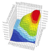
Dual sensored / sensorless adaptive field-oriented sinusoidal mapping (FOC) will allow you to power all brushless motors BLDC on the market.
New product
The OZO 25A dual sensored / sensorless controller incorporates automatic field-oriented mapping (FOC) and very low impedance mosfets to give you performance, comfort, reliability and versatility.
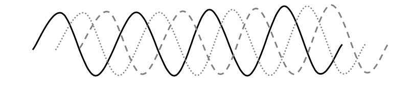
If your Brushless motor is equipped with Hall effect sensors, the curve will be sinusoidal for better comfort.
However, unlike a purely sensored controller, the mapping will automatically switch to sensorless mode in case of failure on one or more sensors, which will allow you to continue driving without losing performance.
If your motor does not have a Hall effect sensor or if you prefer to drive in a square curve to have more torque at startup, simply use the controller without connecting the Hall sensor connector.
Technologie : Dual sensorless / sensored
Hall sensors connected and operational. The output curve of the three phases is sinusoidal. This offers a smoother steering and a quieter engine funcemnet, or even totally silent on a direct drive engine.
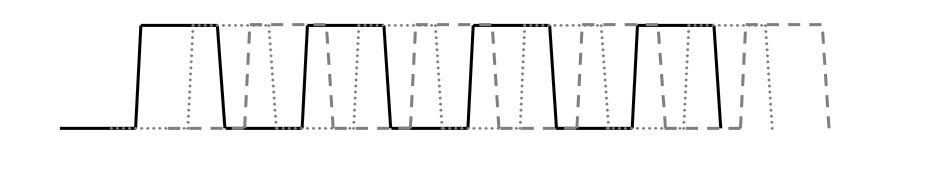
Hall sensors not connected or HS or wire cut, the mapping switches to sensorless mode with a square shape curve output of the three phases is square. The engine will be louder, but the starting torque will be more important.
The different accessories
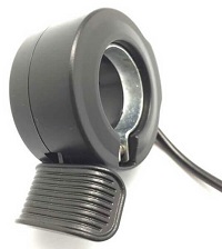
If you want pedaling assistance, you'll need a 12-magnet pedal sensor for better system responsiveness.
The "brake cutoff" connector is used to ground the system. It is advisable to connect a contact brake handle to this connector to shut down the system when braking, but this can also be used for installations with cruise control. To deactivate the regulator, you can use a contact brake handle or a push button on the connector provided for this purpose.
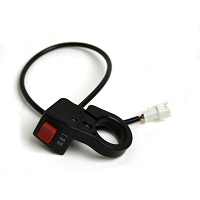
If you want to have an on / off switch on the handlebar, or on the controller, simply cut the pink loop controller output and connect a switch two positions.
Controller diagram
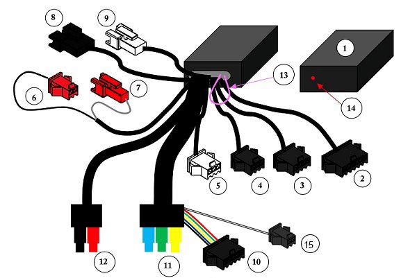
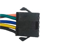
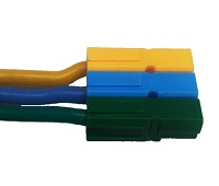
Connectors and cable lengths at controller output
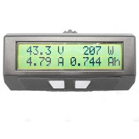
Cycle analyst
(2)
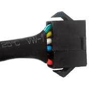
Red: + battery
Black: Mass
Blue: shunt input
White: shunt output
Yellow: signal sensors halls
Green: accelerator signal
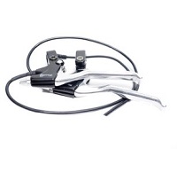
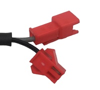
Brake cutoff / Eabs
Connector: 4-way JST for connecting a break brake handle or push button to shut off power to the motor when braking or disabling the cruise control.
Length = 18cm
(3)
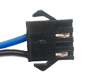
Blue: grounding
Black: Mass
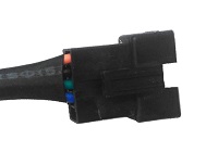
Throttle
Connector: JST 3 way
Length = 15.5cm
(4)
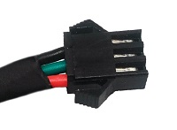
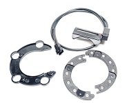
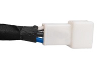
PAS sensor
Connector: JST 3 way white female for connection of a pedal sensor with 6 or 12 magnets.
Length = 15.5cm
(5)
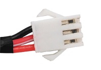
Red: + 5V
White / Red: Signal
Black: Mass
Reverse mode :
JST 2-way red: connect the two connectors together or connect a switch in series to reverse the direction of rotation of the motor.
Length = 13cm
(6) / (7)
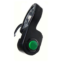
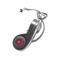
Cruise control
Length = 16cm
(8)
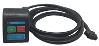
3 speed switch
Length = 15.5cm
(9)
Connectors: Anderson Powerpole PP30 for Power
Length : 80cm
+ 5-way JST connector for Hall sensors: If your motor does not have a sensor, you do not have to connect the JST connector and it will be better to cover it with a heat-shrinkable sleeve to ensure its tightness.
(10)
(11)
Battery cable
Connectors : Anderson Powerpole PP30
Length : 90cm
(12)
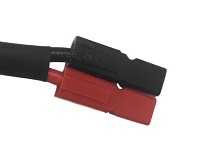
Red : positive terminal
Noir: negative terminal
On-off switch
(13)
Diode for displaying error codes
(14)
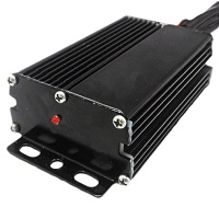
Temperature sensor
(15)
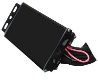
Dimension of the controller

| Guarantee | 2 ans |
| Régulateur de vitesse pour vélo électrique | OUI (en option) |
| Backward mode | OUI |
| Dimensions | 70x105x34mm |
| Connectique pour cycle analyst | OUI |
| Technologie | Dual sensorless / sensored |
| Mass | 340g |
| Connecteur de puissance | Anderson Powerpole PP30 |
| Régénération au freinage | OUI (avec moteur direct drive) |
| Bouton ON/OFF | OUI |
| Cable de puissance | 2,5mm2 |
| Permissible voltages | 12V, 24V, 36V and 48V |
| Tension Max | 60V |
| Compatible cycle analyst | OUI V2 et V3 |
| Coupure frein | OUI |
| Intensité nominale | 25A |
Accessories


- Electric kits
- Ebikes conversion kits with battery
- Kits City and VTC
- MTB
- Road and Gravel
- Others bikes
- Kits without battery
- City bikes Kits without battery
- MTB kits without battery
- Road and Gravel bicycles Kits without battery
- VTC kits without battery
- FAT BIKES Kits without battery
- Folding bikes kits without battery
- cargo bikes kits without battery
- Tricylces kits without battery
- TANDEMS Kits without battery
- Trikes kits without battery
- Kits kids 6 to 12 years old without battery
- Ebikes conversion kits with battery
- Batteries
- Chargers
- Electric Parts
- Accessories
- Solar
- Boating
- Industry
- Docs
- Contact