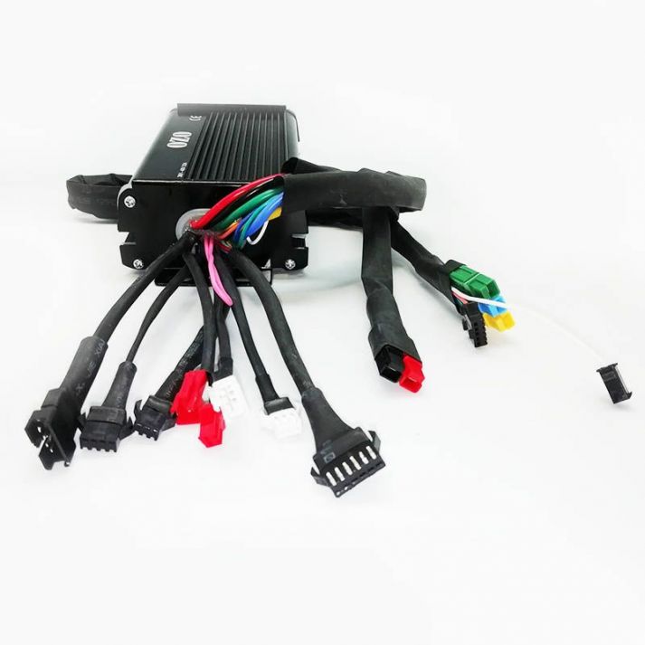
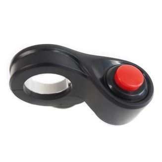
40A 48V to 72V FOC brushless bldc motor controller

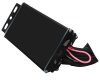
Controller 48V to 72V - 40A dual sensored sensorless for brushless motor.

Compatible with cycle analsyt V2 andV3, throttle, pas sensor, cruise control, backward and forward selection, ebrake cut off, regen

Programmable mapping and automatic swapping from sensored map to sensorless map if hall sensors are damaged.

Recommended with our direct drive brushless BLDC motors from 1500W to 3000W.

More details

000364

New product

179,00 €
ou 3 x 60,65 €

IN STOCK

- +

 
More info
This dual sensored / sensorless controller can drive a brushless motor using the Hall sensors of the motor but unlike a purely sensored controller, it automatically switches to a sensorless mapping in case of failure on one or more sensors.
This controller also manages perfectly the control of motors having a large number of poles (80 poles max). You can power it with 48V to 72V battery
Note: Regeneration will only be possible on a direct drive engine.
The brake cut-off can be used for installations equipped with a pedal sensor or cruise control. To activate the brake cutoff, simply connect a contact brake handle or a push button to the connector provided for this purpose. Note that this controller uses passive regeneration.
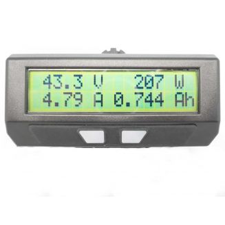
It's possible to connect V2 or V3 cycle analyst directly to the controller and to access all the parameters of your engine and mapping.
This controller get temperature connecteor to connect motor's temperature sensor NTC 10kOhm.
You can note that all OZO motors get this NTC temperature sensor inside.

Technology : Dual sensorless / sensored

Sensored :

Hall sensors connected and operational. The output curve of the three phases is sinusoidal. This offers a smoother steering and a quieter engine funcemnet, or even totally silent on a direct drive engine.

sensored
Sensorless :

Hall sensors are not connected or HS or wire cut, the mapping switches to sensorless mode with a square shape curve output of the three phases is square. The engine will be louder, but the starting torque will be more important.

sensorless

The different accessories

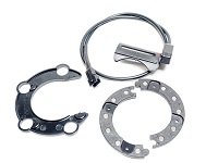
capteur pedalier
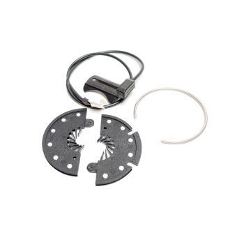
The controller has two control inputs: one for the pedal sensor (12 magnet sensor) and the other for the accelerator. You can choose to control your engine with the pedal sensor and / or accelerator.

If you want pedaling assistance, you'll need a 12-magnet pedal sensor for better system responsiveness.
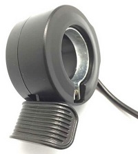
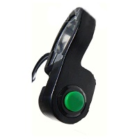
gachette au pouce

The accelerator is independent of the selected modes and the pedal sensor, which means that you can manually adjust the power from 0 to 100% at any time.

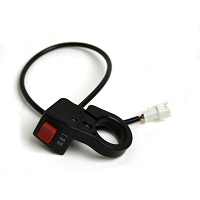
interrupteur 3 positions

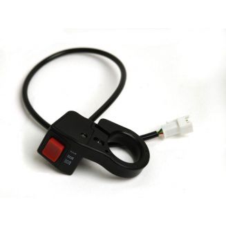
If you want more than one pedaling power mode, you can plug in the three position switch which will allow you to have either: 30%, 60%, or 100% of the maximum power. If you have connected an accelerator and a pedal sensor to the controller, the switch will act on both simultaneously.
Régénération frein
This controller also manages the regeneration, however it will only be possible on a direct drive engine. This is not possible on a "reduced" engine. To activate this mode, simply connect a switch or a break brake handle to the controller.
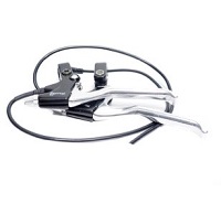
coupure frein

The "brake cutoff" connector is used to ground the system. It is advisable to connect a contact brake handle to this connector to shut down the system when braking, but this can also be used for installations with cruise control. To deactivate the regulator, you can use a contact brake handle or a push button on the connector provided for this purpose.
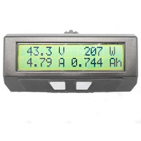
cycle analyst
A 6-way connector connects a V2 or V3 analyst cycle directly to the controller. The analyst cycle will allow you to read and adjust all the parameters of your engine.
régulateur de vitesse
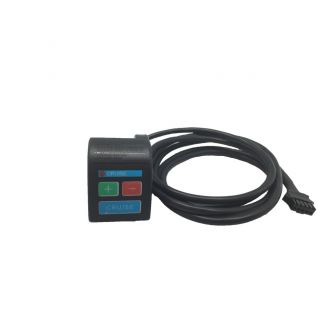
A 5-way connector is used to connect a cruise control box. Its operation is the same as that of a car: you accelerate to the desired cruising speed, then you press the cruise button. You can then release the throttle and the system will vary the power sent to the engine to maintain cruising speed.
interrupteur marche arrêt

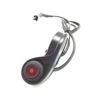
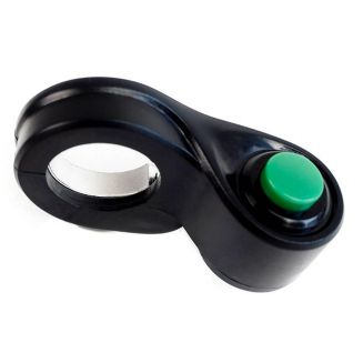
If you want to have an on / off switch on the handlebar, or on the controller, simply cut the pink loop controller output and connect a switch two positions.
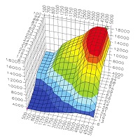
Cartographie moteur
For specific needs, certain parameters of the controller can be parameterized: Max power level and max speed on the three modes, phase current, nominal current, regeneration level, response time ... Do not hesitate to contact our team technical for any customization request. Note that if you use analsalsyt cycle with this controller, you will be able to set all the parameters yourself.

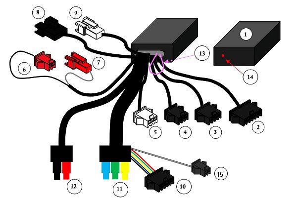
Controller diagram

Schéma controleur

Connectors and cable lengths at controller output

Cycle analyst

Connector: 6-way JST for connecting analsyt V2 or V3 cycle. Length: 18cm

(2)

Cycle Analyst - JST 6 voies femelle

Red: + battery

Black: Mass

Blue: shunt input

White: shunt output

Yellow: signal sensors halls

Green: accelerator signal

Brake cut / regeneration

Connector: 4-way JST for connecting a break brake handle or push button to shut off power to the motor when braking or disabling the cruise control.

Length = 18cm

(3)
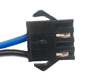
Frein - JST 4 voies femelle

Blue: grounding

Black: Mass

Accélérator

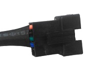
Connector: JST 3 way

Length = 15.5cm

(4)
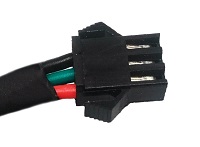
Accélérateur - JST 3 voies femelle
Red: + 5V
Black: Mass
Green: Signal

Crankset sensor 

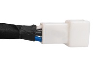
Connector: JST 3 way white female for connection of a pedal sensor with 6 or 12 magnets.

Length = 15.5cm

(5)
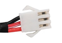
Capteur pédalier - JST 3 voies femelle

Red: + 5V

White / Red: Signal

Black: Mass

Reverse Connector:

JST 2-way red: connect the two connectors together or connect a switch in series to reverse the direction of rotation of the motor.

Length = 13cm

(6) / (7)
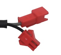
Marche arrière - JST 2 voies

Cruise control

Connector: JST 5 way to connect our cruise control

Length = 16cm

(8)

Régulateur de vitesse - JST 5 voies mâle

Switch 3 position 

Connector: JST 3-way white male to connect our three-position switch, allowing to have three different power modes: 30%, 60% and 100%.

Length = 15.5cm

(9)

Interrupteur 3 position - JST 3 voies mâle
Motor cables

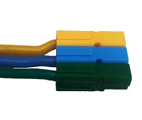
Connectors: Anderson Powerpole PP30 for Power

Length : 80cm

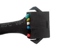
+ 5-way JST connector for Hall sensors: If your motor does not have a sensor, you do not have to connect the JST connector and it will be better to cover it with a heat-shrinkable sleeve to ensure its tightness.

(10)
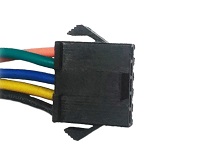
Capteur hall - JST 5 voies femelle

(11)

Moteur - Anderson 3 voies

Battery cable

Connectors : Anderson Powerpole PP30

Length : 90cm

(12)
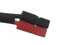
Batterie - Anderson 2 voies

Red : positive terminal

Noir: negative terminal

On-off 

If you want to have a switch on the handlebar or on the controller, simply cut this pink loop and connect our switch two position.

(13)

Marche arrière - JST 2 voies

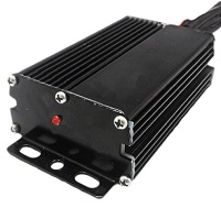
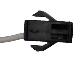
Diode for displaying error codes

The LED flashes in different ways in case of system failure.

(14)

Diode d'affichage

Temperature sensor

Connector: JST 2 way white female for connection of a temperature sensor. Most of OZO motor get a Temperature sensor NTC 10K inside. When motor temperature get 110°C the power is decrease by twice to avoid any thermic issue on motor.

(15)

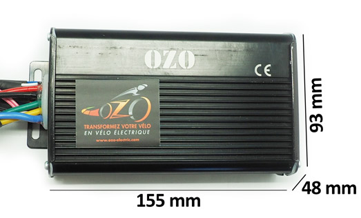
Dimension of the controller

 
Data sheet
Guarantee2 ans
Intensité max40A
poids en 26 pouces785g
Dimensions155x93x48mm
Technologiedual sensored/sensorless sinusoidal
Mosfets12x IRFB4110
Tension d'alimentation48V à 72V DC
Régénération au freinageOUI regen passive
Bouton ON/OFFNON
Tension Max88V
connecteur moteurAnderson et JST

Accessories

Menu